
For an operator on the Norwegian Continental Shelf (NCS), it was important to have an evaluation for how long and where the casing had been exposed to side forces due to drillstring vibration. A transient, stiff-string torque and drag model were used by NORCE to study this case.
A transient, stiff-string torque and drag model that calculates axial, torsional and lateral deformation of the drillstring has newly been developed by the researchers in DigiWells. The model is a combined hydro-mechanical model where the hydraulic forces are included in the lateral dynamics and buoyancy calculation. It includes a drillstring-wall contact model and the drillstring can move axially along the casing/borehole. Verification of this 4n-degrees of freedom transient torque and drag (4nDOF TT&D) model with high frequency downhole measurements from field cases showed very good agreement in complex conditions (Ambrus, Cayeux, & Shor, 2024).
Simulations have been performed using this 4n DOF TT&D model on a case from the NCS to evaluate lateral vibrations and contact loads on the casing.
Simulations
Dynamic simulations considering drilling with an average ROP of 10 m/h and a variable surface RPM have been performed on the case described in Fig 1. Original and processed survey data were used for the well trajectory that was given as input to the model. Four different scenarios and drilling from three different bit depths have been simulated. The operator was especially concerned about the casing wear in a region around 500m MD where the casing shifts from 10 ¾” to 9 7/8” outer diameter (OD).
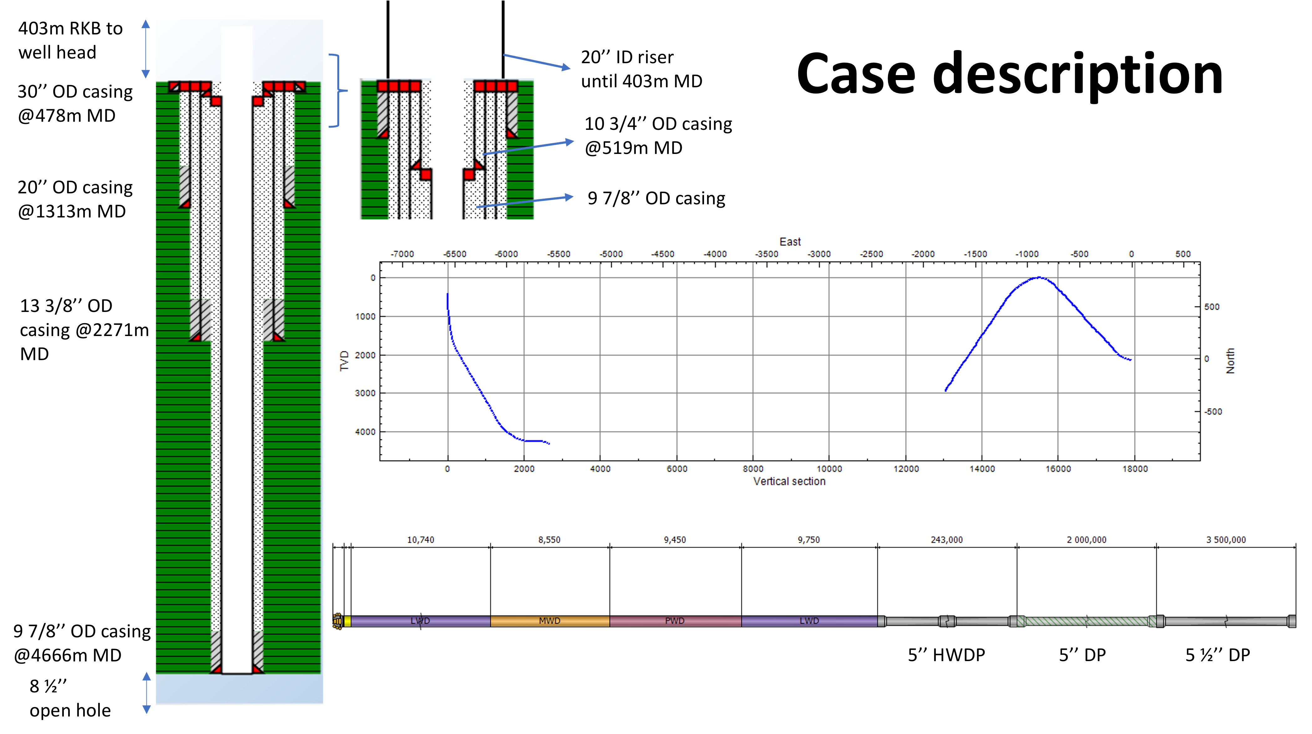 Fig 1: The case description for the simulations. The region of most interest is where the casing shifts from 10 ¾” to 9 7/8” OD.
To estimate a probability distribution for how long and where the casing had been exposed to side-forces, the calculated side force and angle of contact were recorded for each tool joint in contact with the casing. The contact angle is based on the lateral displacement of the tool joint inside a cross-section of the wellbore, and its trend over time can indicate forward and backward whirling, or a more gentle wobbling movement. As tool joints move axially while drilling or hoisting the drillstring, heat maps of the side forces and contact angles on an entire portion of the casing can be constructed. For this purpose, the wellbore was discretized into equally spaced angular sectors and depth intervals. Fig. 2 shows the side forces and the contact angle distribution on the 10 3/4” casing for one of the simulated cases.
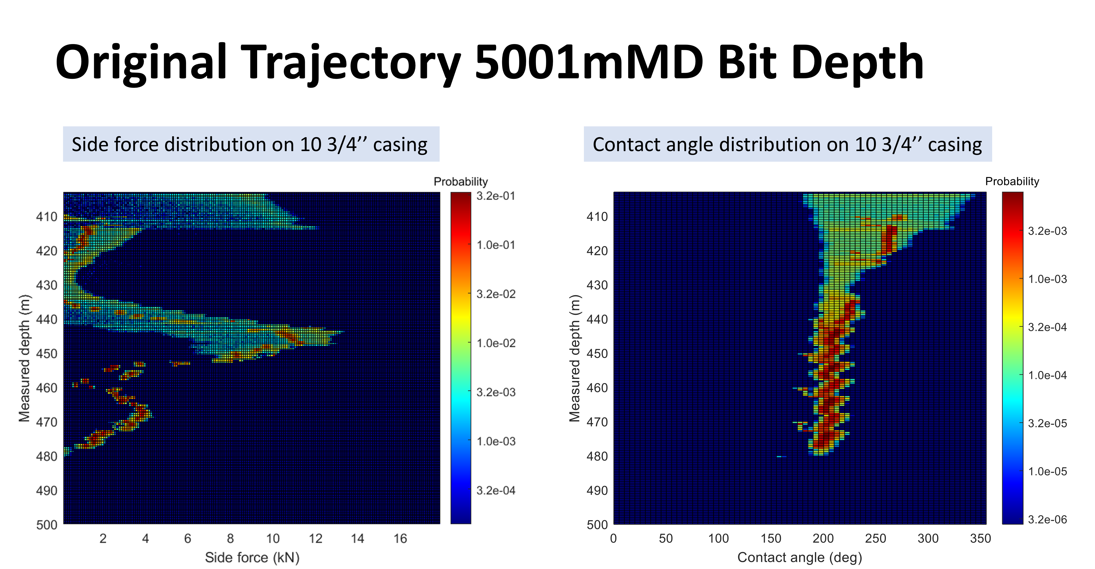 Fig 2: Side forces and contact angle distribution on 10 ¾” casing from 410 m MD to 500 m MD. Red and orange points show higher probability at a particular depth, while green and blue points show lower probability. A wide distribution is equivalent to whirling and a narrow distribution is equivalent to wobbling movement.
Conclusion
Simulations with a 4nDOF model have showed that full whirling can occur in the part of the vertical section of most interest, and that the occurrence of whirl depends on top drive RPM and wellbore tortuosity at shallow depths. The contact force distribution and contact angle can vary significantly over a short depth interval and this has potential implications on casing wear.
Reference
This research study including the images on this webpage are licenced under the CC BY 4.0 license