Challenge
Although automation has greatly improved drilling efficiency, integrating externally managed ADCS functions remains complex. The main risk lies in failures caused by faulty external inputs or parameters, making safety assurance a critical issue. Diverse rigs, tools, and stakeholders complicate reliable deployment and standardization of automated systems. Another challenge is to make automation available also on rigs lacking ADCS.
Innovation
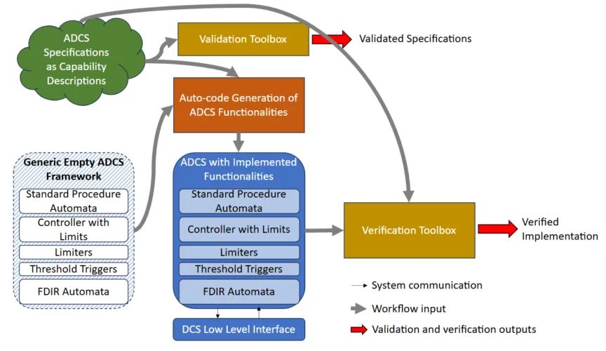
A declarative data model developed by D-WIS enables consistent description of ADCS functionalities. Once validated, corresponding code can be automatically generated using an Auto-code Generator. The resulting code interacts with the low-level DCS interface and make automation possible also on rigs lacking ADCS. The DCS interface has been designed with Safe Mode Management ensuring manual control if communication fails.
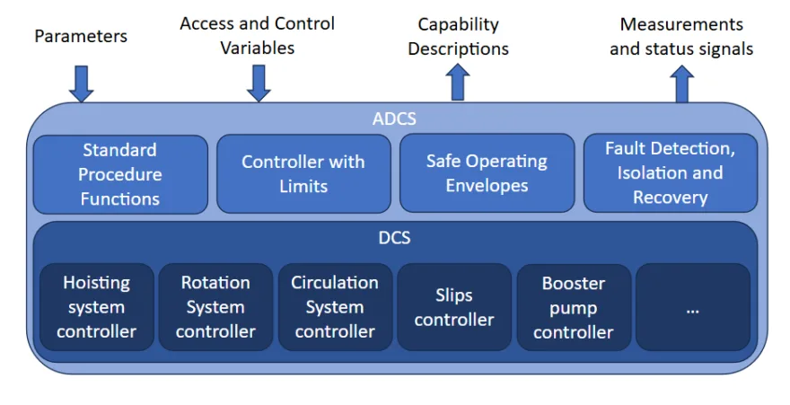
This model supports four ADCS function types:
- FDIR (Fault Detection, Isolation, and Recovery): FDIR functions aim to automatically respond to unexpected drilling events and implement corrective actions to regain control
- SOE (Safe Operating Envelope): SOE functions limit set-points passed to the DCS to ensure that the drilling process remains within safe limits.
- Controllers with limits: Controllers with limits manipulate one process variable to keep other variables within safe bounds. For instance, an auto-driller may control the top-of-string speed to maintain the rate of penetration (ROP) below a maximum, the weight on bit (WOB) under a certain threshold, and the standpipe pressure (SPP) below a set value.
- Automated standard procedures as e.g. a friction test
The framework allows automated testing and mathematical validation of ADCS functions—ensuring reliable execution, avoiding infinite loops, and tracking path coverage.
Value
- Automation can be made available on all rig equipped with computer-controlled drilling machines.
- Establishes a standardized, safe, and scalable pathway for implementing ADCS functionality across rigs.
- Reduces error risk through automated validation and direct alignment of functional descriptions with implementation. (see also Dynamic Verification and Validation)
- This workflow offers the significant advantage of focusing most work at a high level, minimizing reliance on manual coding processes.
- Strengthens resilience in drilling systems while paving the way for future international standards and enhanced operational agility.
Status
Automatic generated ADCS functions have been added to a DCS (Between). Communication with the DCS was done using the low-level interface through OPC-UA. A successful DWIS demonstration including several external automated functions was performed in AkerBP simulator environment.
Next steps
- Development of additional ADCS functionalities
- Refine the formal validation and automatic verification processes
- D-WIS demonstration using automatic generated ADCS functions that includes validation and verification, see Figure 2
This work is part of the centre workpackage 4 Interoperability and the innovation program.

Figure 1—Schematic representation of the different functions of the DCS and of the ADCS and the type of information exchanged with the ADCS.

Figure 2: Schematic representation of the workflow to produce a validated and verified ADCS.
E. Cayeux, R. Mihai, K.K. Olsen, M. Pham. “Code Generation of Automatic Drilling Control System Functions with Embedded Verification and Validation Functionalities” SPE/IADC Drilling Conference 2025. https://doi.org/10.2118/223716-MS
E. Cayeux, J.D. Macpherson, M. Laing, D. Pirovolou, F. Florence, “Drilling Systems Automation: Fault Detection, Isolation and Recovery Functions for Situational Awareness”, https://doi.org/10.2118/212565-MS

